Translate

Bag Filter

Bag Filter- It is used only low teperature application. The cleaned gas will goes through chimney to out and the dust will collect at the hopper

Cyclone

Cyclone- It is used for another types of dust cleaning from gas.

ESP

ESP- Electrostatic Precipitator

ESP

ESP-Electrostatic precipitator. it is most commonly used Dust cleaning machine from Gas. It is Used High temperature application .

Wet Scrubber

Wet Scrubbber- It is used in chemical factories to remove hazardes chemicals from the gas.

Showing posts with label Scrubber- Dry Scrubber. Show all posts

Thursday, March 26, 2015

Summary

Dry scrubbing systems are used to control acid gas emissions primarily from combustion sources such as utility and industrial boilers and municipal and medical waste incinerators. Dry scrubbing systems only remove acid gases and therefore must be followed by a particulate control device (ESP or fabric filter) prior to exhausting the gases to the atmosphere.

Dry scrubbing systems can be categorized as dry sorbent injectors (DSI) or as semi-dry scrubbers (also referred to as spray dryer absorbers or spray dryers). Dry sorbent injection involves the addition of a dry alkaline material (usually hydrated lime or soda ash) into the gas stream to react with any acid gases that are present. The sorbent can be injected directly into the flue gas duct ahead of the particulate control device or into an open reaction chamber. The acid gases are adsorbed onto and react with alkaline sorbents to form solid salts which are removed in the particulate control device.

In spray dryer absorbers (SDAs) the flue gases are introduced into an absorbing tower (dryer) where the gases are contacted with a finely atomized alkaline slurry: usually a calcium-based sorbent such as Ca(OH)2 or CaO. Acid gases are absorbed by the slurry droplets and react to form solid salts. The heat of the flue gas is used to evaporate all the water droplets, leaving a non-saturated (i.e. dry) flue gas exiting the absorber tower. The effect of cooling and humidifying the hot gas stream increases collection efficiency over simple dry injection.

The major components of a spray dryer absorber are the atomizer, spray dryer chamber and the particulate control device. Two types of atomizers are currently utilized for acid gas removal: rotary disks (wheel type) and dual-fluid nozzles. In either case, the purpose of the atomizer is to break the sorbent slurry into a cloud of fine droplets. The spray chamber is designed based on the type of atomizer utilized. Spray chambers used with rotary atomizers are shorter but fatter than those used with two-fluid nozzle atomizers. Both ESPs and baghouses have been used with spray dryer absorbers. An important design feature of the particulate control device is to minimize potential heat loss in the fly ash collection system to prevent potential plugging problems.

An important parameter in the operation of a dry scrubbing system is the amount of alkaline material feed into the system. The amount of sorbent required is a function of the type of sorbent used, inlet and outlet (required removal) acid gas levels and the effectiveness of the dry scrubbing system design. The amount of sorbent added is generally reported as the stoichiometric ratio on a molar basis of sorbent to acid gases. A stoichiometric ratio of 1:1 would be used under ideal conditions; in practice more than the theoretical amount must be utilized to assure compliance with required acid gas removal levels.

Except for rotary atomizers in spray dryers, dry scrubbing systems are relatively simple devices with few moving parts. The primary maintenance problem is potential plugging in the solid or slurry transport lines. Plugging can occur whenever there are bends or restrictions in piping.


Wednesday, March 25, 2015

Maintenance Problems

Except for rotary atomizers in spray dryers, dry injectors and spray dryer absorbers are relatively simple devices with few moving parts. The primary maintenance problem associated with any dry scrubbing system is potential plugging in the solid or slurry transport systems. Manufacturers of the various systems provide suggested maintenance and inspection schedules for each component. These schedules should be followed and information recorded to aid in documenting the system operation.

Dry scrubbing systems involve transporting a solid or slurry (which can be 10 to 40% solids) in small pipes; therefore, plugging problems could occur in a number of locations. The most common locations of plugging problems are in "dead" areas of the solid or slurry piping, valves and the atomizer. Dead areas of piping are associated with tees going to spare pumps or a cleanout port. In these areas, flow only occurs occasionally and provides an area for solids to buildup and block transport lines. Eliminating the tees is not practical since redundancy is needed (and often mandated) in order to assure continual operation of the scrubbing system. Also, certain tees are installed specifically to allow quick access to piping internals in order that a specific length of pipe can be flushed with water to dislodge buildup. Flexible rubber hosing and quick-type connectors have been used to try and minimize line plugging. Flexible piping is not as susceptible to plugging as solid pipe, and with the use of quick connectors, the flexible piping can be installed or removed quickly to flush out areas or to connect spare components.

Plugging problems associated with valves and atomizers in slurry systems are minimized by using screens in transport lines to remove solids. However, these screens must be periodically checked and cleaned or else they will cause plugging. Atomizing systems are often designed so that they can be flushed with water during operation (this will temporary reduce potential acid gas removal efficiency). Atomizers should also be designed so that they can be replaced in a short timeframe.

Another area of maintenance with semi-dry scrubbing systems is the lime slaking system. Lime slaking is the process of mixing controlled amounts of water and lime in a mixing vessel (slaker). The lime and water react (an exothermic process) to form the lime slurry which is then screened of grit, stored in agitated mixing tanks and then metered to the atomizer.

With the slaking system, plugging and the quality of slurry produced are the two biggest maintenance concerns. Plugging of dead spots and pumps can occur as already discussed. In addition, the grit screening process is of concern because if the screen is damaged, then large quantities of grit can get into the entire lime-slurry transport system causing extensive plugging and/or abrasion wear problems. Slurry quality is dependent on the quality of lime and slaking water utilized in addition to the mechanical action of the slaker. Both the lime and water should be of high quality (limited contaminants or other chemicals present) to prevent adverse reactions that can result in scaling, plugging or reduced acid gas removal efficiencies. The mechanical action of the slaker will determine how efficiently the slaking reaction occurs. The slaker should be frequently inspected to ensure that it is operating as designed.

Plugging of lime slurry transport components can also occur due to a lack of slurry movement (i.e. during standby periods) when solids could settle out or the calcium could have time to react and form scale. During extended downtimes, lines and storage tanks should be drained and flushed where practical. Also, manufacturers recommend periodic cleaning in acid of screens and other components that are prone to plugging problems.


Tuesday, March 24, 2015

Spray Drying Equipment

In a spray drying system, there are a number of system components. Three of the major components are the atomizer, spray dryer chamber and particulate control system.

Atomizers
Currently, two types of atomizers are used in spray dryers for acid gas removal: rotary disks or wheels and dual-fluid nozzles. In either case, the purpose of the atomizer is to break the sorbent slurry into a cloud of fine droplets to promote intimate sorbent contact with the acid bases.

In the rotary atomizer, the slurry is fed into the top of the rotating wheel or disk. Centrifugal force causes the slurry to form a thin film on the internal surface of the cavity. As the slurry emerges from the cavity through abrasion-resistant inserts in the side of the wheel, the liquid is atomized into discrete droplets that are propelled radially outward. These droplets, generally 25-150 μm in diameter, dry rapidly in the hot flue gas within the spray dryer. Figure 1  shows an example of a typical atomizer wheel used in spray dryers (Huang 1988).

Figure 1. Example of rotary atomizer used in spray-dryer FGD
systems

For FGD spray dryer applications, atomizer wheels range from 8 to 16 inches in diameter and have rotational speeds from 7,000 to 20,000 revolutions per minute (rpm). Due to the highly abrasive nature of the slurry (which can consist of either slaked lime [Ca(OH)2] or slaked lime plus recycled fly ash/reacted product), the wheels are constructed of corrosion- and abrasion-resistant materials, including ceramic inserts in the vanes or nozzles.

In dual-fluid pneumatic nozzle atomization, the slurry feed is injected into the body of a nozzle and is entrained into a high-velocity, high-pressure air stream as shown in Figures 2 and 3 (Maurin 1983). The high-velocity air impacts on the slurry-feed stream, resulting in the production of fine droplets. The air stream and slurry comprise the two fluids. The size of liquid droplets produced decreases as the compressed air pressure and relative velocity of the liquid to air increases.

Figure 2. Two-fluid nozzle atomizer (nozzle body)

Figure 3. Two-fluid nozzle atomizer (high pressure air stream)

The mean droplet size for both atomizing systems has been shown to be the same, indicating that the systems perform similarly. Likewise, the capacity of a nozzle system for atomization of slurries is the same as that for a rotary atomizer. Nevertheless, rotary atomizers and pneumatic nozzles have somewhat different advantages and disadvantages (Huang 1988):

1. Rotary atomizers, with their higher capacity per unit, will have a simpler piping system. In a rotary-atomizer system, usually only one feed pipe per atomizer is used; whereas in a nozzle-type atomizer, there will be an individual feed pipe (and valve) to each nozzle. In very large installations, this results in a complex piping system.

2. Pneumatic nozzle atomizers are much easier to maintain than rotary atomizers while the system is on-line because the individual feed lines have isolation and control valves. With multiple nozzles, it is possible to isolate an individual nozzle, remove it for cleaning or replacement, and then return the cleaned or new nozzle to service without reducing the gas flow to the system or bypassing the gas flow to another spray dryer.

3. The net-energy requirements of a rotary atomizer and a set of pneumatic nozzles are approximately the same, but the method by which this energy is applied is different. For a rotary atomizer, the atomization energy is supplied via a motor coupled to the atomizing wheel with a gear and/or belt drive. For a pneumatic atomizer, the energy of atomization is produced primarily by the pressure of the atomizing air. Hence, the energy is supplied through an air compressor that may also supply air for instrumentation or other purposes.

4. A spare rotary atomizer is often required as a backup in case of failure. In a pneumatic nozzle system, the required spares consist of nozzles and an extra air compressor. For a smaller single rotary-atomizer unit, the relative cost of a spare atomizer would be substantial

Spray-Dryer Chamber

The atomization method chosen will affect the design of the spray-dryer chamber, including the physical dimensions. For a rotary-atomizer type of spray dryer, which projects the droplets radially outward and perpendicular to the gas flow, the length-to-diameter ratio of the dryer (L/D) is typically 0.8:1. Figure 4(A) illustrates two typical configurations of rotary atomizer spray dryers. The droplets decelerate rapidly due to the drag forces of the downward-moving flue gas and eventually attain the speed and direction of the flue gas. To avoid wall deposition, the designed radial distance between the atomizer and the dryer wall must be sufficient to allow for adequate drying of the largest droplets. This is accomplished by proper choice of the L/D, droplet size, and residence time.

For a two-fluid pneumatic nozzle spray dryer [shown in Figure 4(B)], which atomizes the droplets in the direction of the gas flow (downward), the L/D is typically 2:1. In this case, sidewall deposition is a minor problem.

Typically, industrial boiler spray dryers have diameters of 25-30 ft, whereas utility spray dryers have diameters of 40-50 ft. Currently, the maximum diameter of an installed spray dryer is about 60 ft. In general, if the gas-flow rate is large enough that a single unit greater than 40-50 ft in diameter would be specified, then the installation of multiple spray dryers should be considered. In utility systems where the gas flow can range from 1-2 million acfm, multiple spray dryers are common. Multiple spray dryers are installed for easy maintenance and high reliability.

Flue gas may enter a spray dryer in one of three patterns relative to the slurry direction: cocurrent, countercurrent, or mixed. In cocurrent spray dryers, all of the gas enters through a roof gas disperser in the top of the vessel, where its rotation is controlled by angled vanes that direct the gas around the atomizer [shown in Figure 4 (A)]. This type of gas distribution precisely controls the exit gas temperature since the gas and slurry travel in the same direction. This is the most common flow pattern used in acid gas control systems.

In countercurrent spray dryers, the gas enters from the bottom of the vessel and is directed at the atomized liquid above. Although uncommon in utility or industrial flue-gas control systems, these spray dryers have the advantage of a much higher drying capacity than the cocurrent system.

Another type of spray dryer, the compound-gas disperser or mixed, is offered by one manufacturer as an option in specific applications. This type of spray dryer is sometimes used on very large units as an alternative to multiple rotary atomizers to obtain efficient contact between the hot gas and the liquid droplets.

Figure 4. Two types of spray-dryer chambers

Particulate-Matter Collection

A spray-dryer system is not complete without a means of particulate-matter collection. Not only is a well-designed particulate-matter control system needed to meet emissions requirements, but it also aids in acid-gas removal. Acid gases are removed when the flue gas comes in contact with lime-containing particles in the fabric filter or ESP. Fabric filters have been used on the majority of acid gas control systems, due to their ability to obtain slightly higher residual acid gas removal than ESPs.

Regardless of the type of particulate control device, an important design feature is to minimize potential heat loss in the fly ash collection system. The fly ash contains unreacted alkaline sorbent along with calcium (or sodium) sulfates, and in the case of waste incinerators, it also contains calcium chlorides. These materials are very hygroscopic and can result in corrosion problems or ash plugging of equipment if condensation occurs. Adding insulation, hopper heaters and reducing air in-leakage are essential to prevent operational problems with the ash handling system.


Saturday, March 21, 2015

Operating and Design Parameters

Key design and operating parameters that affect spray dryer design and/or performance are:

• Flue gas flow rate and composition
• Temperature of flue gas exiting the boiler and spray dryer
• Alkaline stoichiometric ratio
• Alkaline (lime or sodium) properties
• Required removal efficiency

The most important parameter in sizing the spray dryer is to ensure an adequate gas residence time at maximum gas flow rate to prevent wet solids at the spray dryer outlet. Gas residence times are generally in the range of 10 to 15 seconds for most commercial systems. Due to the large volume of gases that must be treated from utility boilers, these installations often have multiple dryers per boiler.

The spray dryer outlet temperature is controlled by the amount of water injected either with the alkaline slurry or as makeup water. The key to achieving good SO2 removal is to maintain the temperature of the flue gas exiting the spray dryer as close above its dew point (adiabatic saturation) as possible without actually saturating the flue gas. Generally, 20 - 30°F above the adiabatic saturation point is a good target range. This will enhance the reaction yet still prevent condensation. The amount of water that can evaporate in a spray dryer is dependent on the incoming flue gas temperature and to a lesser extent on the moisture content.

The alkaline feed rate is a function of the incoming acid gas levels and the required removal efficiency. The stoichiometric ratio is defined as the molar ratio of alkaline (i.e. calcium) in the spray dryer feed to the amount of acid gases (SO2 and HCl) present. For example, at a ratio of 1.0 the moles of calcium are equal to the moles of incoming HCl and SO2. However, due to inefficiencies in the mixing process, more than the theoretical amount of alkaline material is required to assure compliance with applicable standards. Thus, stoichiometric feed rates of 1.5 to 2.5 have been used to achieve SO2 removal level in the 75 to 85% range and HCl removal efficiencies of 95% on municipal waste combustors. For utility and industrial boilers, sulfur removal guarantees by spray dryer vendors have ranged from 60 to 90%. Table 1 lists information on operating spray dryer systems at utility boilers.

Summary of spray-dryer applications
                           1. R = rotary; N = nozzle.
                           2. Residence time.
                           3. Flue-gas temperature at entrance.
                           4. Approach to saturation at exit.
                           5. Varies.
                           6. Not reported.
                           Source: Huang et al. 1988.


Friday, March 20, 2015

Spray Dryer Systems

In the spray drying process, an alkaline slurry [usually Ca(OH)2] is injected into a spray dryer chamber through either a rotary atomizer or two-fluid nozzle injectors.

The atomized slurry droplets contact the hot flue gas in the spray dryer chamber (See Figure 1). The water in the alkaline (lime) slurry evaporates to cool the flue gas, and the lime reacts with the acid gases in the flue gas to form calcium- or sodium-based salts. The reaction or absorption chamber is designed to provide sufficient contact and residence time to produce a dry product leaving the chamber. The particulate exiting the chamber contains fly ash, calcium salts and unreacted lime that must be sent to a particulate control device, usually a fabric filter or electrostatic precipitator (ESP).

Fig.1 Spray dryer absorber

Collected solid reaction products from the system are sometimes recycled to the feed of the spray dryer to reduce alkaline sorbent use. Figure 2 provides a diagram of a typical spray drying system. The major components of a typical spray drying system are:

• Alkaline (lime) storage and slaking system
• Alkaline mixing and feed tanks
• Atomizer (rotary or nozzle)
• Spray dryer chamber
• Particulate control device (e.g. baghouse)
• Recycle system (optional)

Fig.2. Components of a spray dryer absorber system

Thursday, March 19, 2015

Dry Injection

Dry sorbent injection (DSI) is a process used to control acid gases by injecting a powdered sorbent into the flue gas stream. The sorbent can be injected into the furnace, boiler area or the ductwork/reaction chamber prior to the air pollution control device. The injection point depends on the type of sorbent and required reaction time. For example, some sorbents need to be injected at elevated temperatures to undergo a decomposition reaction before they can effectively remove the acid gas. Figure 1 shows a schematic of a typical dry injection system.
Components of a dry injection system

The dry sorbent injection system is a very simple system that consists of a dry sorbent storage tank, a weight feeder to meter the required amount of sorbent, a blower and transfer line, and an injection device such as a venturi. The dry sorbent material is blown through a pneumatic line to the injection area where transfer through the pneumatic line provides fluidization of the sorbent material. Injection into the duct is generally done countercurrent to the gas flow to create added turbulence and promote mixing. An expansion/reaction chamber may be included to increase the residence time of the acid gases to react with sorbent.

The simple dry injector process described above is capable of achieving moderate control of acid gasesfor example 50% SO2 and 90% HCl removal on municipal and medical waste combustors. The acid gas removal efficiencies can be increased by cooling and/or humidifying the flue gas stream. Exhaust gases from industrial boilers or refuse combustors can range from 600oF to 400oF. The flue gases can be cooled (and the humidity increased) by using a heat exchanger or a dry quench chamber upstream of the injection point. Cooling the flue gas temperature increases the rate of reaction between the sorbent and acid gases. But, the temperature must be maintained high enough (300-350oF) to ensure that all the water droplets used to quench are evaporated.

Recycling a portion of the collected particles and unreacted sorbent is another method used to increase overall effectiveness of dry scrubbing systems. As stated previously, it is difficult to mix a dry solid and a gas stream; therefore, additional sorbent (above stoichiometric amount) must be injected. As a result, there is unreacted sorbent captured in the baghouse or electrostatic precipitator. In some instances a portion of this waste stream is recycled back to the injection point.

In order to achieve high removal efficiencies using relatively inexpensive calcium sorbents, most dry injection systems have to operate at higher stoichiometric ratios than a spray dryer would. For example, stoichiometric ratios of 2.0 to 4.0 are used on municipal waste combustors to achieve moderate acid gas control. This increased sorbent usage limits their application to smaller sources such as medical waste incinerators. Table 1 lists some facilities that have installed dry injection acid gas control systems.

Examples of dry injection systems on medical and municipal
waste incinerators


Tuesday, March 17, 2015

Stoichiometry

An important parameter in the operation of a dry scrubbing system is the amount of alkaline material feed into the system. The amount of sorbent required is a function of the following:

1. The type of sorbent used
2. The inlet and outlet acid gas levels (the outlet level is determined by removal requirements)
3. The effectiveness of the dry scrubbing system design

The amount of sorbent added is usually reported on a molar basis as the stoichiometric ratio of sorbent to acid gases.

Although the sorbents are either calcium- or sodium-based solids, the exact chemical reaction that occurs depends on the type of sorbent used and the injection point in the process. Presently the most widely used dry scrubbing system is the calcium-based hydrated lime [Ca(OH)2]. A slurry of hydrated lime and water is injected into the spray dryer and reacts with the acid gases in a simplified manner as follows:

Ca(OH)2 + SO2 → CaSO3(s) + H2O

Ca(OH)2 + 2HCl → CaCl2(s) + 2H2O

As you can see from the above reactions, one mole of calcium hydroxide [Ca(OH)2] will neutralize one mole of SO2, whereas one mole of calcium hydroxide will neutralize two moles of HCl.

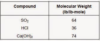
To compute the pounds of calcium hydroxide required to neutralize a given weight of SO2 or HCl, the molecular weight of each component must be utilized. For example, the molecular weights of SO2, HCl, and Ca(OH)2 are as follows:


Therefore, one pound of calcium hydroxide can neutralize 0.86 pounds of SO2 (64 divided by 74) or 0.97 pounds of HCl (36 times 2 divided by 74).

In computing the stoichiometric ratio of a system, all the acid compounds in the waste stream need to be accounted for. Also, the above equations are for the stoichiometric quantities of sorbent. The actual use of sorbent will be above these quantities because of normal inefficiencies in operation; contact of sorbent and acid gases is never ideal and distribution of acid gases in the flue gas is often not uniform (especially in incineration systems). The actual stoichiometric ratios can range from as low as 1.5 to 4.0 dependent on system design and required removal efficiencies.

Similar type reactions occur with sodium-based compounds. For semi-dry systems using caustic soda (NaOH) the following simplified reactions can be written:

SO2 + 1/2 O2 + 2NaOH → Na2SO4 + H2O

HCl + NaOH → NaCl + H2O

Also, sorbents react with different acids at different rates. For example, sorbents react with chlorides at a faster rate than with SO2. Therefore, in waste streams that have both SO2 and HCl, the HCl is removed at a higher rate than the SO2.


Monday, March 16, 2015

Gas Removal Mechanisms

In dry scrubbing, acid gas is removed by the mechanisms of adsorption and absorption. In dry injection systems, where adsorption is the primary removal mechanism, pollutant gas molecules adhere to the surface area of the alkaline particles. Thus, the reaction between the acid gas and the alkaline material takes place on the surface of these alkaline particles. The alkaline materials are generally calcium hydroxide or sodium-based reagents that have the consistency of a fine powder. These fine particles have large surface areas to aid in adsorbing the acid gases.

In spray dryer systems, absorption is the predominant collection mechanism. Absorption can occur in conjunction with a chemical reaction if a reagent has been added to the scrubbing liquid. Spray dryer absorbers utilize this principle. First, the acid gas dissolves in the alkaline slurry droplets, then reacts with the alkaline material dissolved therein to form solid salts. Because the acid gases react to form new compounds, additional acid gases can be absorbed by the liquid. Also, when the liquid droplets evaporate, the acid gases continue to react (by adsorption) with the solid alkaline materials remaining in the SDA.

Adsorption and absorption are similar mass transfer processes in that the acid gases must first be brought into contact with the alkaline sorbent material, be provided ample reaction sites and time, and finally, be removed from the gas stream. Intimate contact between the alkaline sorbent and acid gases is important for effective gas removal. With dry injection, solid powder-like sorbent is dispersed in either the furnace area, exhaust duct, or in a reaction chamber. Dispersion is generally provided by injecting the sorbent through a venturi device countercurrent to the flow of the gas stream to create turbulence. In spray dryers, the alkaline sorbent slurry is dispersed as a mist of tiny liquid droplets in the reaction or drying vessel. Due to their fine spray mists, spray dryers provide much more contact area than dry injectors for gas absorption to occur. Also, spray dryer absorbers provide more effective mixing of acid gases with the alkaline sorbent than dry sorbent injectors because it is easier to mix a gas with a liquid than with a solid. Spray dryer absorbers have some disadvantages; the injection (atomization) equipment required by spray dryer absorbers is much more complicated and expensive to operate.

Residence or reaction time can be enhanced in these applications in a number of ways. In dry injectors, the sorbent is often injected directly into the furnace or ductwork. To extend the residence time, reaction or holding vessels can be added to the dry sorbent injection system. Spray dryers always have a reaction or drying chamber to assure a dry gas stream leaving the chamber. Also, in both systems, the particulate control device will provide an additional area for the acid gases to further react with the sorbent.

In addition, both the absorption and adsorption processes are temperature dependent: the cooler the flue gas, the more effectively the acid gases will react with the sorbents. Spray dryer absorbers cool the gas stream and therefore, can achieve higher removal efficiencies than dry injection with no cooling.

Saturday, March 14, 2015

Dry Scrubber

Dry scrubbing systems control acid gas emissions (SO2, HCl, HF, etc.) and are used primarily on utility and industrial boilers, municipal waste combustors, medical waste incinerators, and some refinery processes. Of course, wet scrubbing systems can also function effectively as acid gas collectors. Regardless of whether scrubber acid gas control systems operate wet or dry, they have a mechanism for introducing alkaline material into the exhaust gas to react with the acid gases present.

Up to this point, you have been learning about wet scrubber designs. In wet scrubbers, liquid droplets provide the primary targets for collecting particles and gases. To facilitate this process, gas streams are saturated with moisture; therefore wet scrubbing systems release a steam plume when exiting the stack. Also, wet scrubbers require a system of pipes and pumps for collecting, treating, and recirculating the scrubbing liquid. In contrast, as their name implies, dry scrubbers either operate completely dry or use much smaller amounts of liquid than wet scrubbers. In some semi-dry designs, liquid is added to the alkaline material, creating a slurry. High scrubber temperatures evaporate the moisture before the gases and reaction products leave the scrubber. Therefore, dry scrubbing systems do not have a stack steam plume or waste water handling/disposal requirement.

There are a number of different dry scrubbing systems designs. However, all consist of two main sections or devices: (1) a device to introduce the acid gas sorbent material into the gas stream, and (2) a particulate-matter control device to remove reaction products, excess sorbent material and any other particulate pollutants in the flue gas. Dry scrubbing systems can be categorized as dry sorbent injectors (DSIs) or as spray dryers [also called semi-dry scrubbers or spray dryer absorbers (SDAs)]. Since dry scrubbing systems only remove gases, a separate device is always required to remove particles. The particulate control devices are generally fabric filters or electrostatic precipitators (ESPs).

Dry sorbent injection involves the addition of a dry alkaline material (usually hydrated lime or soda ash) into the gas stream to react with any acid gases that are present. The sorbent can be injected directly into the flue gas duct ahead of the particulate control device or into an open reaction chamber. The acid gases react with alkaline sorbents to form solid salts which are removed in the particulate control device.

In spray dryer absorbers, the flue gases are introduced into an absorbing tower (dryer) where the gases are contacted with a finely atomized alkaline slurry [usually a calcium-based sorbent such as Ca(OH)2 or CaO]. Acid gases are absorbed by the slurry mixture, and react to form solid salts. The heat of the flue gas is used to evaporate all the water droplets leaving a non-saturated (i.e. dry) flue gas exiting the absorber tower. The effect of cooling and humidifying the hot gas stream increases collection efficiency over simple dry injection.